How to Read a Circuit Board for Beginners and Common Troubleshooting Tips
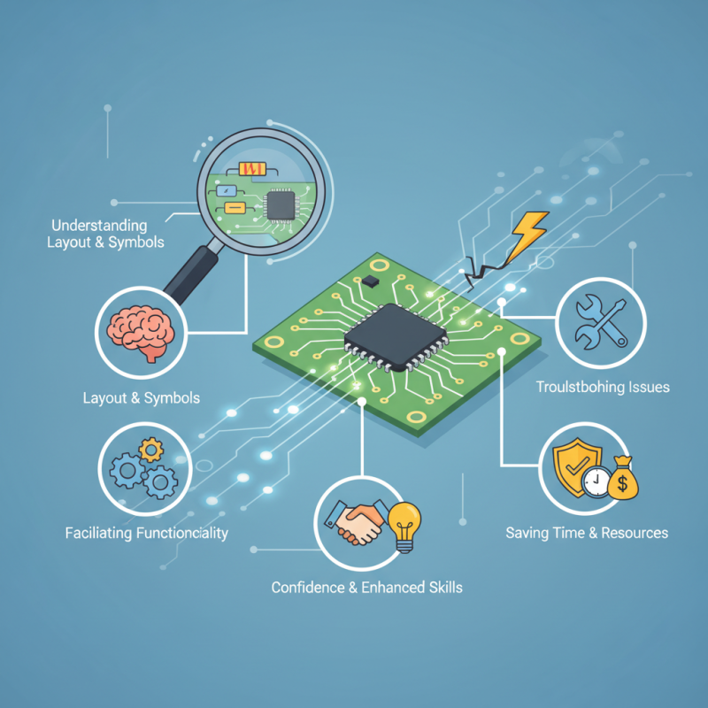
Understanding how to read a circuit board is essential for anyone interested in electronics, whether you're a beginner looking to repair devices or a hobbyist eager to delve into circuit design. A circuit board serves as the backbone of electronic devices, connecting components to facilitate functionality. By comprehending the layout, symbols, and pathways of a circuit board, you can begin to troubleshoot issues effectively, saving time and resources.
In this introductory guide, we will explore the fundamental aspects of reading a circuit board, highlighting key components such as resistors, capacitors, and integrated circuits. Additionally, we will provide common troubleshooting tips to identify and resolve issues that may arise in various electronic devices. With this knowledge, you'll be equipped to navigate the complexities of electronic circuits with confidence, enhancing your skills and understanding in the ever-evolving field of technology.
Understanding the Basic Components of a Circuit Board
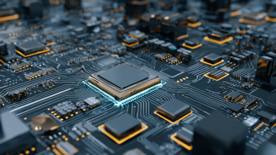
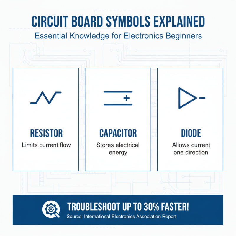
Understanding the basic components of a circuit board is essential for anyone looking to familiarize themselves with electronics. A circuit board is typically made up of various elements such as resistors, capacitors, diodes, and integrated circuits. Resistors are used to limit the flow of current, while capacitors store and release electrical energy. Diodes allow current to flow in one direction, and integrated circuits combine multiple functions into a single chip, making them crucial for complex operations.
When examining a circuit board, it’s important to recognize the layout and function of these components. Each piece plays a specific role, and their arrangement can indicate how the circuit operates. For example, power supply components often cluster in one area, supplying energy to other parts. Understanding these basics not only aids in reading circuit schematics but also helps in troubleshooting issues. If a device isn't functioning properly, identifying which component is malfunctioning can often lead to a quick fix. Whether you’re repairing a faulty gadget or building your own electronics, having a solid grasp of these fundamental components is the first step towards successful circuit board navigation.
How to Read a Circuit Board for Beginners and Common Troubleshooting Tips
| Component |
Function |
Common Issues |
Troubleshooting Tips |
| Resistor |
Limits current flow |
Overheating or incorrect value |
Check with a multimeter for resistance value |
| Capacitor |
Stores electrical energy |
Leakage or bulging |
Visual inspection and capacitance test |
| Diode |
Allows current to flow in one direction |
Short circuit or open circuit |
Test with a multimeter in diode mode |
| Transistor |
Amplifies or switches electronic signals |
Failure to switch |
Test the base-emitter and collector-emitter junctions |
| PCB traces |
Conduct electricity between components |
Broken or damaged traces |
Use a continuity tester to check for breaks |
Identifying Circuit Board Symbols and Labels for Beginners
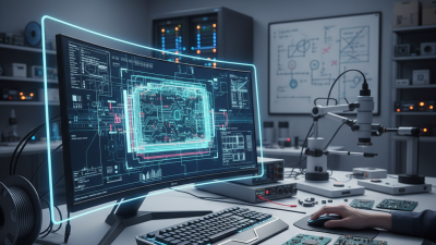
Understanding circuit board symbols and labels is essential for anyone beginning to dive into electronics. Circuit boards are typically marked with various symbols that represent different components and functions. Common symbols include resistors (represented by a zigzag line), capacitors (two parallel lines), and diodes (a triangle pointing to a line). According to an industry report published by the International Electronics Association, familiarizing oneself with these symbols can increase troubleshooting efficiency by up to 30%. This statistic highlights the importance of recognizing component symbols not only for assembly but also for effective repair and maintenance.
In addition to symbols, labels on circuit boards often include numerical or alphanumeric codes that provide crucial information about the connections and configurations of components. For example, ‘R1’, ‘C1’, and ‘U1’ typically refer to the first resistor, capacitor, and integrated circuit, respectively. A report from the Electronics Industry Association indicates that understanding these labels can reduce the likelihood of errors during assembly by 25%. By accurately reading and interpreting these labels, beginners can significantly enhance their ability to identify issues like short circuits or misplaced components, ultimately leading to a more systematic approach to circuit troubleshooting.
How to Use a Multimeter for Circuit Board Testing
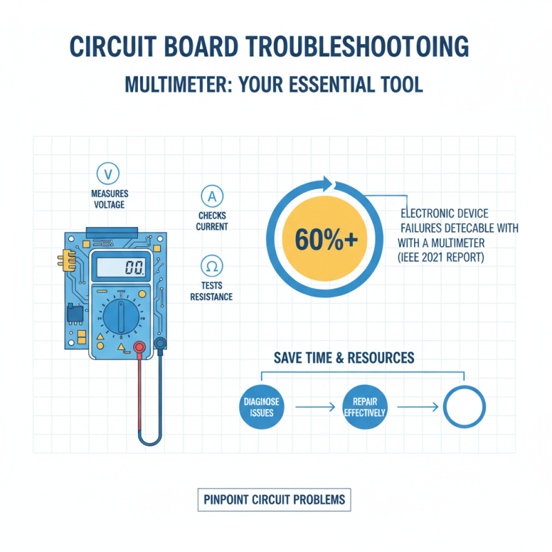
Using a multimeter is essential for anyone looking to troubleshoot circuit boards. This versatile tool allows users to measure voltage, current, and resistance, making it invaluable for pinpointing issues within an electronic circuit. According to a 2021 report by the Institute of Electrical and Electronics Engineers (IEEE), over 60% of electronic device failures can be traced back to issues detectable with a multimeter. Whether you're dealing with a simple resistor malfunction or a more complex integrated circuit failure, knowing how to properly utilize a multimeter can save time and resources in the diagnostic process.
To start testing, ensure your multimeter is set to the appropriate mode—voltage (AC or DC), current, or resistance—based on what you are measuring. For instance, when assessing a voltage drop across an element, connect the probes across that component and read the displayed value. A significant deviation from the expected voltage could indicate failure. Statistics from the Electronic Industries Alliance (EIA) highlight that nearly 45% of technician time is spent on tasks related to troubleshooting, and efficient use of a multimeter can reduce this time significantly, enhancing overall productivity in the repair process. By mastering these skills, beginners can improve their confidence and accuracy when diagnosing circuit board problems.
Common Circuit Board Issues and How to Diagnose Them
When troubleshooting a circuit board, identifying common issues is essential for effective diagnosis. One frequent problem occurs due to visual signs such as burnt components or broken traces.
Burnt components often appear discolored or may have physical damage like cracks or charring. In such cases, replacing the damaged component is necessary to restore functionality. Broken traces can sometimes be repaired by soldering a small wire across the gap, allowing the circuit to maintain connectivity.
Another common issue is poor solder joints, which can result in intermittent connections. Inspecting solder joints under magnification may reveal cracks or incomplete connections. Reflowing the solder or adding more solder can enhance the connection reliability. Additionally, checking for solder bridges—where solder unintentionally connects two points—can help prevent short circuits, which can lead to greater circuit board damage. By being aware of these issues and their visual indicators, beginners can efficiently troubleshoot and maintain circuit boards.
Effective Repair Techniques for Circuit Board Problems
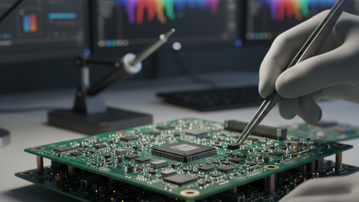
Effective repair techniques for circuit board problems require a systematic approach and the right tools. When faced with issues on a circuit board, the first step is to conduct a thorough visual inspection. Look for obvious signs of damage such as burnt components, broken traces, or discolored areas. Utilizing a magnifying glass can aid in identifying tiny cracks or issues that may not be visible to the naked eye.
Once potential problem areas are identified, using a multimeter to test for continuity can help isolate faulty components or circuits.
In cases where components need replacement, soldering skills are essential. It’s important to use the appropriate tools, such as a soldering iron with a fine tip, and to practice safe soldering techniques to avoid further damage. Removing damaged components carefully requires a steady hand and possibly a desoldering pump to extract old solder efficiently.
After replacing components, remember to check all connections thoroughly to ensure they are secure. Additionally, if the circuit board is complex, documenting the repair process step-by-step can provide clarity and assist in future troubleshooting efforts. By combining keen observation with meticulous repair techniques, beginners can effectively address circuit board issues and enhance their troubleshooting capabilities.