
Why Choose Diaphragm Wall Equipment for Your Project?

Deep excavations leave little room for error. In dense urban sites, nearby buildings, utilities, and groundwater can quickly complicate foundation work. Diaphragm Wall Equipment helps contractors build reinforced concrete walls in confined spaces, often before excavation begins. Typical systems use a hydraulic grab or hydromill, supporting slurry, reinforcement cages, and tremie concrete. The method is powerful, but not effortless.

The need for careful planning is growing. UN DESA’s World Urbanization Prospects: The 2018 Revision projects that 68% of the global population will live in urban areas by 2050. More urban development can mean deeper basements and tighter construction sites. UNEP and the Global Alliance for Buildings and Construction report that buildings and construction accounted for 32% of global energy demand and 34% of energy-related CO₂ emissions in 2023. These figures do not measure diaphragm wall performance. They do, however, underline why project teams should consider material use, logistics, and construction efficiency early.

Choosing equipment means matching capability to ground conditions, wall depth, panel dimensions, and site access. A grab may suit some projects; harder strata may require a hydromill. Slurry quality, verticality checks, and reliable concrete placement matter just as much as machine capacity. Small setup mistakes can become expensive underground. There is no universal best choice. This guide examines where Diaphragm Wall Equipment can offer practical advantages, what to assess before procurement, and which limitations deserve honest attention.
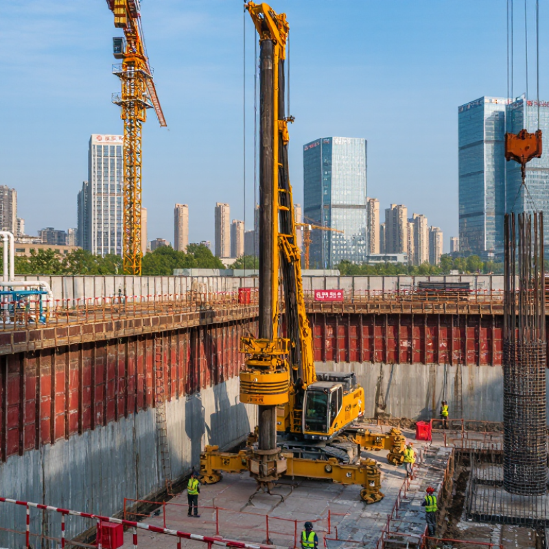
Why Choose Diaphragm Wall Equipment for Your Project?

What Diaphragm Wall Equipment Is and How It Works

Diaphragm wall equipment is a coordinated set of machines used to excavate and construct reinforced concrete walls underground. A guide wall keeps the trench entrance aligned, while a hydraulic grab or cutter removes soil in narrow panels. Cranes handle the tools and lift reinforcement cages. The exact setup depends on ground conditions, wall depth, and available working space.

As excavation progresses, bentonite or polymer slurry supports the trench sides and helps limit collapse. Pumps circulate the slurry through a treatment plant, where screens and desanders remove soil particles before reuse. Once a panel reaches its design depth, workers lower in a steel cage and place concrete through a tremie pipe from the bottom upward. The rising concrete displaces the slurry, which is collected for treatment. The sequence sounds straightforward. Site conditions rarely are. Unexpected gravel or slurry loss can slow the work, so monitoring and adjustments matter.

Tips: Check slurry properties and trench verticality regularly, not only at the end of excavation. Confirm that the crane can safely reach the panel and lift the cage. Small errors travel. Keep records of depth, slurry tests, and concrete placement; they help explain problems, though they cannot prevent every delay.

Key Components of a Diaphragm Wall Equipment System

A diaphragm wall system is more than a grab or cutter. It is a coordinated set of equipment: the excavation machine, crane, slurry plant, desanding unit, tremie pipes, and reinforcement cage handling gear. Each part affects wall quality. A stable crane positions the tool over the guide wall; slurry tanks keep support fluid available; and desanding equipment removes excavated fines before slurry returns to the trench. Small delays matter. If the slurry plant cannot keep pace, excavation may pause while the trench remains open.

Slurry testing is a practical measure of system performance, not paperwork. EN 1538:2010+A1:2015 gives common pre-concreting checks, including slurry density around 1.15 g/cm³ maximum and sand content around 4% maximum; project specifications may differ. CIRIA’s C760 guidance also emphasizes matching construction methods and quality controls to ground conditions. Operators should check funnel viscosity, density, and sand content, then record results by panel. A clean reading does not prove the trench is perfect. This is easy to overlook. The grab’s wear, cable alignment, and panel verticality deserve regular checks too. Equipment selection should consider excavation depth, soil layers, access, and spoil handling—not only rated capacity. The right setup reduces avoidable stoppages, though no machine can erase poor planning.

Why Choose Diaphragm Wall Equipment?

Key components work together to excavate and construct deep, reinforced concrete walls in a controlled sequence.

Guide walls align the panel; a grab or hydromill excavates the trench while support slurry helps stabilize it. After trench cleaning, a crane lowers the reinforcement cage, and concrete is placed through a tremie pipe, displacing the slurry. Sequence numbers indicate order, not duration or performance.

How Diaphragm Wall Construction Proceeds Step by Step

Why Choose Diaphragm Wall Equipment for Your Project?

Diaphragm wall construction begins with site checks and guide walls. Crews confirm ground conditions, underground services, wall depth, and working space. Guide walls mark the alignment and help keep excavation equipment on course. Small details matter. The sequence looks tidy on paper; the site rarely does.

Specialized equipment excavates the wall in separate panels, using a grab or milling system suited to the soil and required depth. As the trench deepens, bentonite or polymer slurry supports its sides and helps prevent collapse. Operators monitor slurry properties and excavation verticality throughout the work. Once a panel reaches its design depth, crews clean the trench bottom and install a prefabricated steel cage. Lifting needs careful coordination, especially where overhead clearance is limited.

Concrete is placed from the bottom upward through a tremie pipe, displacing the supporting slurry as the panel fills. Teams check concrete delivery, cage position, and slurry recovery, then record key measurements for quality control. Panel joints need particular attention because poor preparation can create leakage paths. The right equipment can improve control and reduce delays, but it cannot replace experienced operators or sound ground assessment. Planning may still need adjustment when actual soil conditions differ from investigation results.

Why Choose Diaphragm Wall Equipment for Your Project? - How Diaphragm Wall Construction Proceeds Step by Step

Step Construction Stage Typical Equipment Key Dimensions and Quality Checks Why It Matters
1 Review ground and design conditions Ground-investigation tools, survey instruments, and design records Review soil and rock layers, groundwater level, adjacent structures, wall depth, thickness, and excavation sequence. Wall dimensions are project-specific; common thicknesses are approximately 0.6–1.5 m. Ground conditions and project constraints determine the suitable excavation method, support-fluid plan, and panel sequence.
2 Set out the wall and build guide walls Survey equipment, excavator, formwork, and concrete-placement tools Mark the wall alignment and panel limits. Construct guide walls to control the trench position and provide a stable reference for excavation equipment. Accurate alignment at the surface helps control verticality and position throughout excavation.
3 Excavate the panel Hydraulic grab or hydromill trench cutter, selected for ground conditions Excavate to the approved panel width, thickness, and founding depth. A grab is commonly used in suitable soils; a cutter can be selected where deeper excavation or harder strata require it. The right excavation system can improve trench accuracy and productivity while addressing the site's geology.
4 Support the trench with slurry Slurry mixing plant, storage tanks, pumps, desander, and testing equipment Maintain the specified support-fluid level and properties during excavation. Check fluid characteristics, such as density, viscosity, and sand content, against the project specification. Support fluid helps limit trench collapse and control groundwater inflow before the concrete is placed.
5 Check trench depth and cleanliness Depth-measuring device, verticality monitor, and desanding system Verify excavation depth, panel geometry, verticality, and trench-base condition. Remove excessive sediment and confirm acceptance criteria before reinforcement installation. Inspection helps reduce defects and ensures the panel is ready for reinforcement and concreting.
6 Install reinforcement cage and joint form Crawler crane, lifting frame, reinforcement cage, and stop-end or joint-forming system Lift and lower the cage using an approved lifting plan. Check cage dimensions, splice details, cover provisions, embedments, and joint alignment against the drawings. Controlled handling protects the cage and helps maintain the required structural detailing and panel-to-panel connection.
7 Place concrete by tremie Tremie pipes, concrete supply vehicles, and concrete testing equipment Place concrete continuously from the bottom upward through tremie pipes, keeping the discharge embedded in fresh concrete as required by the method statement. Record delivery and placement details. Tremie placement displaces the support fluid and helps produce a continuous concrete panel under slurry.
8 Complete, inspect, and proceed to adjacent panels Survey instruments, concrete records, joint-cleaning tools, and excavation equipment Record concrete volume and levels, check the finished panel and joints, and follow the approved sequence for primary and secondary panels. Continue with adjacent panels as specified. Consistent sequencing and documented checks support wall continuity and provide traceability for construction quality.

Note: Dimensions and equipment choices shown are indicative only. Final methods, tolerances, and material acceptance limits should follow the project design, geotechnical conditions, applicable standards, and approved method statement.

Project Conditions Suited to Diaphragm Wall Equipment

Why Choose Diaphragm Wall Equipment for Your Project?

Project Conditions Suited to Diaphragm Wall Equipment

Diaphragm wall equipment can suit deep excavations in dense urban areas, especially where nearby buildings leave little room for open slopes. Its equipment forms reinforced concrete panels below ground, helping create a stiff retaining wall. Groundwater matters. The method may be practical where water-bearing soils make excavation control difficult, but slurry management and panel sequencing need careful planning.

Site access, soil layers, and excavation depth all affect equipment selection. A compact work area may still need space for cranes, slurry tanks, spoil handling, and concrete delivery. In mixed ground, cutting rates can change sharply between soft clay and hard inclusions. A site may look suitable on drawings, yet buried obstructions or restricted overhead clearance can complicate the work. Check the rig envelope. Early geotechnical review and a realistic construction sequence help reveal these constraints before mobilization.

Tips: Compare the planned wall depth with proven equipment reach, and confirm crane setup space on site. Review groundwater levels, adjacent foundations, and spoil routes with the project team. Keep a contingency for slower excavation; estimates are not guarantees.

Factors for Choosing Diaphragm Wall Equipment

Choosing diaphragm wall equipment starts with ground conditions, wall depth, and site access. Review bore logs, groundwater levels, and hard layers before comparing machines. A cutter system may suit deep panels and variable strata, while a grab can work well in softer, less obstructed ground. The choice is not automatic. Panel dimensions and required verticality matter too. Check working depth, lifting capacity, and guidance methods against the design, rather than relying on headline capacity alone.

Space can change the decision. Measure delivery routes, overhead clearance, and room for slurry tanks, cranes, and spoil handling. On a tight urban site, a large rig may meet technical needs but slow other tasks. Compare mobilization time, operator skill requirements, maintenance support, and compatible tool availability. Ask how the equipment performs when actual ground differs from survey findings; that gap is easy to underestimate. Assess noise, vibration, and slurry management against site constraints. Request performance data and review service records where possible. The cheapest machine may not deliver the lowest overall cost. Still, estimates can be wrong. Recheck assumptions before procurement.