Radio frequency printed circuit boards (RF PCBs) are specialty PCBs that assist with receiving and transmitting radio signals. They’re designed to operate on high-frequency signals above 100 megahertz (MHz), making them suitable for small devices like smartphones and a wide range of other uses.
Learn more about RF PCBs and their standard applications.
Depending on the board’s application, the manufacturers will use different materials to increase specific characteristics such as thermal durability and environmental resistance. The following materials are some of the most common in RF PCBs.
FR4 refers to a standard published by the National Electrical Manufacturers Association (NEMA) that provides requirements for flame-retardant (FR), glass-reinforced epoxy laminate materials. These materials typically include a fiberglass-epoxy resin composite and are cost-effective and easy to source, making them suitable for various high-frequency and high-temperature applications.
Some of the top benefits of using FR4 as a substrate include:
Rogers materials are PCB laminate materials manufactured by Rogers Corporation. These materials, such as Rogers 4003 and Rogers 4350B, are designed specifically for PCBs operating at extremely high RF and microwave frequencies.
Key properties of Rogers materials include:
These materials are popular across various industries, such as telecommunications, consumer electronics, and aerospace and defense.
Polytetrafluoroethylene (PTFE) is a thermoplastic polymer, which means it has exceptionally high thermal resistance. It also features a low dielectric constant and loss tangent, so it provides a stable signal even in high-frequency applications.
Based on your board’s intended application, you may need to add PTFE reinforcement or fillers to ensure reliable functionality. It can help to discuss your needs with an experienced designer who can recommend the right board features and materials.
PCBs must be highly conductive and stable to ensure optimal performance. Adding a layer of copper foil enhances PCB function by:
Copper is also an easy metal to solder, making it an efficient choice for manufacturing purposes. It’s usually applied on one or both sides of the laminate, depending on your requirements.
Ceramic materials like aluminum oxide are often used as alternatives to epoxy-based substrates like FR4 and Rogers materials. They offer the following benefits to RF PCB operations:
These properties allow ceramic to act as a stable, rigid platform for electronic components and circuits.
Finally, the manufacturer must apply a series of protective layers to the board’s copper pads and traces to enhance solderability and reduce the risk of oxidation. This surface coating, known as a conformal coating, can be made of various materials depending on your application requirements:
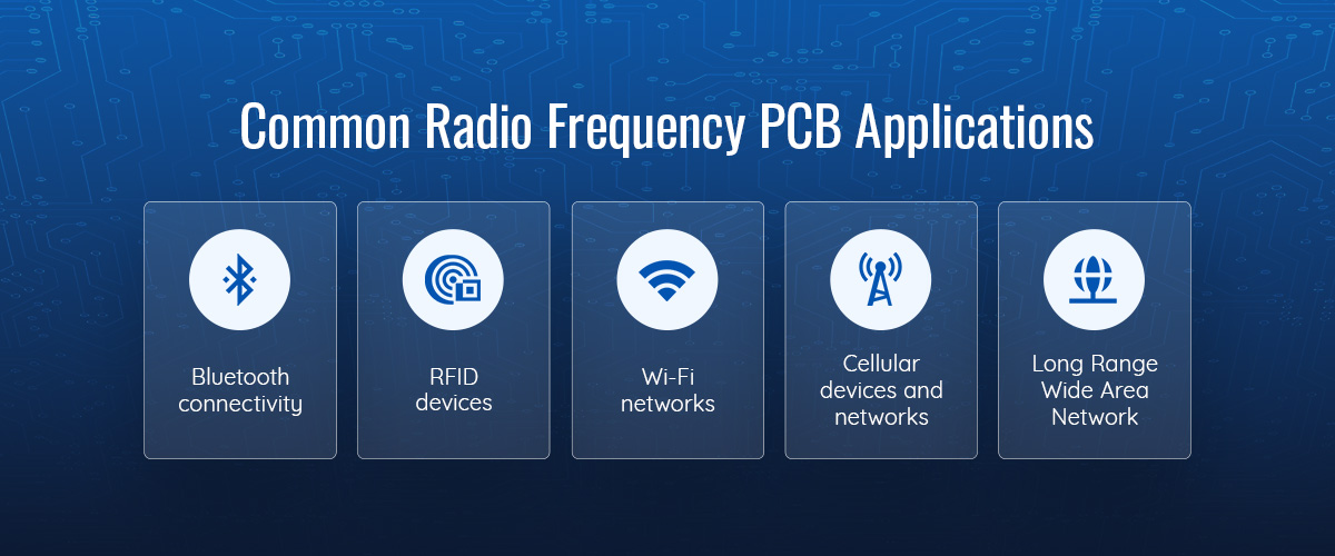
RF PCBs are most commonly used in wireless communication applications where they will receive and transmit high-frequency signals. Some examples of wireless standards that use RF PCBs include:
These applications are numerous and span across various sectors, such as medical devices and aerospace systems. For example, mobile phones are only made possible with RF PCBs. On a much larger scale, satellite communications for aerospace and defense purposes rely on RF PCBs to provide consistent signals with high frequencies.
When you’re designing a printed circuit board, you must create a functional design that meets your specific requirements before beginning manufacturing.
Some essential RF PCB manufacturing considerations include:
Because they can handle signals at such high frequencies, RF PCBS are significantly more complex than standard printed circuit boards. Multilayer layouts are typically best for this type of PCB, which usually requires the designer to take additional steps and considerations for layer-to-layer interactions during manufacturing.
Choosing the right RF PCB material and bonding material is another important consideration based on environmental and budgetary needs. If you need help choosing the right components, layout or materials for your printed circuit board, getting in touch with a professional design and manufacturing company like Via Technology can help you get started.
Knowledgeable PCB experts can advise you on board customizations tailored to your unique specifications, so you can get the optimal board for your intended application.
Are you interested in manufacturing products requiring RF PCBs? The experts at Via Technology are your first choice for technological design engineering solutions. We have more than 30 years of experience working with clients in multiple industries, which guides us in designing custom solutions with fast turnaround times and unmatched attention to detail.
Contact us today to learn more about how we can assist with your project. Our online quote form can quickly get you started with product design so you can cut time to market and launch at the optimal time.