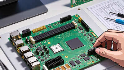
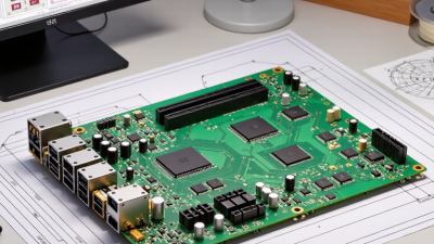
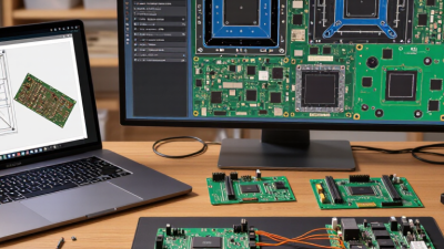
Choosing a circuit board design service is not just a search for low quotes. Global buyers need teams that can turn electrical requirements into buildable, testable boards. The difference often appears in practical details: a clear layer stack-up, controlled-impedance notes, readable fabrication files, and a reviewer who catches a connector conflict before production. Small oversights can become costly delays. That is worth remembering.
A useful perspective comes from Henry Ott, an EMC expert and author: “The best way to solve EMC problems is not to create them in the first place.” His advice matters during layout, when grounding, return paths, and component placement can shape electromagnetic performance. A capable provider should explain these choices, document assumptions, and flag unresolved risks—not promise that every design will work perfectly on the first revision.
This guide to the 2026 best circuit board design services for global buyers focuses on evidence buyers can compare: engineering capabilities, communication practices, design-for-manufacturing checks, revision control, and support after handoff. Ask for relevant project examples and confirm what each service includes. A polished portfolio is useful, but it cannot prove fit for your board. Even a careful comparison has limits; requirements, timelines, and supplier workflows differ. The right partner is the one whose process matches your needs and whose engineers can explain trade-offs in plain language.

A dependable PCB design service turns an electrical idea into files that a fabricator and assembler can use. Schematics define connections, component values, and signal relationships. Clear net names and reviewed symbols help prevent confusing handoffs. Designers should confirm connector positions, power needs, and operating conditions with the buyer before layout begins. Small assumptions can become costly board changes.
Layout places components and routes copper while balancing signal integrity, heat, size, and assembly access. Design for manufacturability (DFM) checks whether trace widths, spacing, drill sizes, and solder-mask openings fit the chosen process. Verification may include design-rule checks, schematic-to-layout comparison, and review of manufacturing outputs. A clean report helps, but it cannot replace engineering judgment. Even experienced teams can overlook a late component change, so revision tracking matters.
Tips: Share the enclosure outline, connector locations, and preferred stack-up early. Ask for native design files and a concise DFM report. Check critical footprints against component datasheets. One detail is easy to miss: confirm that test points remain reachable after assembly.

Global PCB output reached US$73.4 billion in 2024, reflecting the scale of demand for electronics across many industries. This figure describes board output, not revenue earned by design-service providers. Still, it signals a crowded, technically demanding supply chain. Buyers should look beyond price and ask how a design team handles layout constraints, component availability, and manufacturing feedback. A compact board may look elegant on screen but prove difficult to assemble. Details matter.
Tips: Share the enclosure dimensions, expected production volume, and operating conditions before requesting a quote. Ask for design files and review notes, not only rendered images. Confirm how the provider checks signal integrity, thermal behavior, and manufacturability. Small oversights can mean another prototype.
Market growth does not guarantee a smooth project. A service provider may offer fast initial layouts yet communicate poorly when test results require changes. Ask who reviews the design and how revisions are documented. A useful review should flag concrete risks, such as a connector too close to an enclosure wall or limited space around a heat-producing component. Some requirements will change mid-project; that is normal. Buyers should still record assumptions clearly, because informal decisions are easy to forget.
A dependable circuit board begins with measurable requirements, not a preferred shape or component list. Define the operating voltage, current, temperature range, signal speeds, connector positions, and expected production volume. Record enclosure limits and mounting-hole locations too; a board that fits electrically may still collide with a screw boss. Small details matter. Review the schematic and flag sensitive analog paths, fast edges, and high-current loads before placement. We sometimes discover that an early assumption was wrong, such as leaving too little room for a cable bend. It is cheaper to correct that now.
With requirements agreed, establish the layer stackup, copper weight, board thickness, and fabrication tolerances with the intended manufacturer. Then place connectors and mechanical features, followed by critical components and routing. Apply IPC-2221 spacing guidance as a design baseline, checking the relevant tables for voltage, insulation conditions, and conductor location. Do not treat one clearance value as universal. Keep return paths continuous, separate noisy power routes from delicate signals, and add test points where probes can reach them. Run design-rule checks, inspect the layout visually, and verify manufacturing outputs against the approved stackup. A clean report helps, but it does not catch every awkward assembly detail. Show the draft to the assembly team; their practical feedback can expose problems the layout screen hides.
Estimated current capacity for external copper traces at a 10°C temperature rise, using 1 oz copper (approximately 1.37 mil thick).
Estimates use the IPC-2221 empirical conductor-current relationship. Actual allowable current depends on board construction, copper thickness, thermal conditions, and design constraints; verify trace sizing for the specific application.
2026 Best Circuit Board Design Services for Global Buyers
A reliable supplier evaluation starts with the board’s actual use, not a generic capability sheet. Check whether the supplier can build to the relevant IPC-6012 class and document acceptance criteria before quoting. Ask for sample inspection records, not just a claim of compliance. For a dense multilayer design, review how the team handles annular rings, impedance requirements, and drill-to-copper clearances. Small details matter. DFM feedback should identify specific risks, such as a narrow solder mask dam or an impractical via location, and suggest workable changes.
Testing and delivery estimates need equal scrutiny. Confirm which electrical tests are included, such as continuity and isolation, and whether microsection analysis or impedance coupons are available when required. Ask how lead time changes if materials are delayed or a design revision arrives late. A clear schedule should distinguish fabrication, testing, and shipping. It may still change. That is worth acknowledging early. Review IP controls, too: ask who can access design files, how transfers are secured, and how long records are retained.
Tips: Send the same controlled drawing package to each candidate, then compare written responses line by line. Request a short DFM review before placing a production order. Keep revision numbers visible on every file; a small oversight here can cause expensive confusion.
Global sourcing works best when board technology follows a product’s real constraints, not a supplier’s broad capability list. For a compact sensor, HDI can route fine-pitch components through tighter spaces and reduce board area. Ask for the proposed layer stack, via structure, minimum trace width and spacing, and a sample impedance report. A capability sheet alone is not proof. Request cross-sections or test coupons from a comparable build, then confirm which specifications the supplier will guarantee in writing.
Rigid-flex suits products that need fewer cable connections or must bend inside a tight enclosure. Share the bend radius, bend direction, expected movement, and mechanical drawings before requesting a quote. Static bends and repeated flexing place different demands on copper and coverlay. Assembly matters too: confirm component sourcing controls, soldering methods, inspection coverage, and defect reporting. A video call can clarify factory processes, but it cannot replace a pilot run. Pilot runs matter. Use production materials and fixtures, then review yield, warpage, and electrical test results. Compare landed cost, lead time, engineering response, and change-control practices—not just unit price. Forecasts can still be wrong; early plans often overlook fixture delays or slow approvals. Leave time for a design revision.
| Service capability | Best suited to | Key technical checks | Assembly considerations | Request before sourcing |
|---|---|---|---|---|
| Standard multilayer PCB | General electronics, control boards, and products without unusually dense routing or repeated bending. | Confirm layer stack-up, copper weight, finished board thickness, minimum feature capability, and applicable acceptance class. | Check component sourcing, soldering processes, inspection coverage, and whether testing is included. | Request a DFM review, proposed stack-up, fabrication drawing review, and a clearly itemized prototype and production quote. |
| HDI PCB | Compact products with high component density, fine-pitch packages, or routing constraints that benefit from high-density interconnect structures. | Discuss microvias, via filling and capping, sequential lamination, registration, stack-up design, and the relevant IPC-2226 design approach. | Verify that land patterns, solder-mask clearances, stencil design, and assembly inspection suit the component pitch and board design. | Ask for a manufacturability assessment of the actual Gerber or ODB++ data, microvia reliability details, and cross-section or qualification evidence where needed. |
| Rigid-flex PCB | Products needing a compact interconnect, reduced connector count, or a board section that flexes during installation or use. | Review flex-layer materials, bend radius, bend location, copper type, stiffeners, coverlay, and the rigid-flex stack-up; align requirements with IPC-2223 design guidance. | Plan panel support and handling during assembly, and keep components and solder joints out of dynamic bend areas unless the design is specifically validated. | Provide bend and installation details; request a stack-up review, fabrication drawing review, and confirmation of testing and inspection for the flex sections. |
| PCB fabrication plus assembly | Buyers seeking one coordinated workflow for bare-board fabrication, component procurement, assembly, and testing. | Confirm board specifications, revision control, material traceability, and the applicable fabrication requirements, such as IPC-6012 for rigid boards or IPC-6013 for flexible and rigid-flex boards. | Clarify SMT and through-hole processes, component substitutions, traceability, inspection criteria, and whether functional testing is included. | Request a bill-of-materials risk review, approved-substitute list, assembly process plan, and separate pricing for fabrication, parts, assembly, and testing. |
| Prototype and low-volume assembly | Engineering validation, pilot builds, and products whose design or demand is still changing. | Check whether the proposed design is manufacturable at the intended volume and whether prototype materials and processes match the planned production design. | Confirm lot-size limits, component availability, build documentation, rework controls, and inspection reporting. | Ask for lead-time assumptions, non-recurring charges, sample inspection records, and a process for handling engineering changes between builds. |
| Production-scale sourcing | Established designs requiring repeat orders, predictable quality controls, and supply-chain planning across regions. | Evaluate process controls, change management, material approvals, lot traceability, and the quality requirements stated in the purchase documents. | Agree on acceptance criteria, inspection sampling, electrical testing, packaging, and any product-specific reliability or compliance requirements. | Request a documented quality plan, capacity and lead-time assumptions, change-notification terms, and a sample of the inspection and shipment records. |
Sourcing note: Manufacturing limits, lead times, certifications, and inspection options vary by supplier and project. Confirm the current capability against the released design files and written purchase requirements. IPC standards provide industry guidance; specify the applicable revision and acceptance criteria in the project documentation.